Swept Amplitude Modulation (SAM)
Effective angle countermeasures against lobe scanning radars, aiming to mislead the tracker as the actual target angle, need to synchronize their modulation patterns with the motion of the radar beam.
This is possible when the radar employs a single beam for both transmission and reception; the jammer is able to synchronize the motion of the detected transmitted beam (Conical Scan radars).
In order to avoid to be jammed an effective radar Counter-Counter-Measure (CCM) is to employ separate transmitting and receiving antennas with the non-scanning transmitting antenna providing constant illumination at the target, (the jammer receives a flat, not modulated, signal).
Such systems are referred to as Lobe-On-Receive-Only (LORO) or Scan-On-Receive-Only (SORO) systems.
Against LORO or SORO radars, the jammer is forced to operate a technique of Amplitude Modulation blindly, with a far less effect than if synchronized.
This technique requires a high J/S technique and assumes the knowledge of the scan rate of the victim radar (Mission Data dependent).
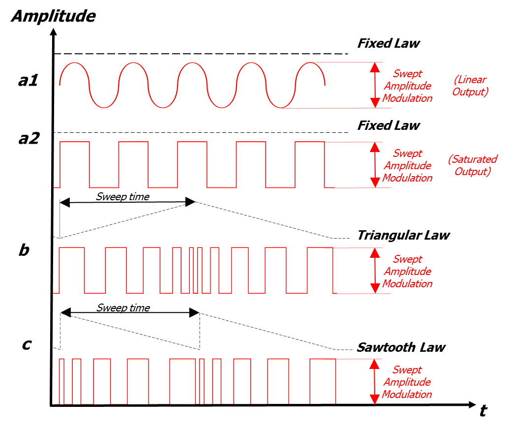
Based on the knowledge of the precise scan frequency ωR of the radar, the jammer generates a false target that moves in circle about scan axis by transmitting a constant frequency value ωJ (case a1 and a2 of Figure 1) very close to the radar one.
The jammer signal produces a false target angle rate slow enough to be followed by the tracker, creating an equivalent error θj such as to generate a break lock.
The maximum angle rate that can be tolerated involves that ωJ must be very close to ωR in order appreciable effects to be obtained.
In order to enhance oscillation effects in the radar receiver additional frequency modulations (case b and c of Figure 1) can be added to the ON-OFF modulation.
This technique is called Swept Amplitude Modulation (SAM) Deception Technique.
SAM produces an ON-OFF Amplitude Modulation, whose Repetition Interval is frequency modulated around the value of the scan rate of the radar.

• Case a1 and a2: Fixed modulation produces a constant rate of change between the two amplitude levels.
• Case b: Triangular modulation produces a rate of change between the two amplitude levels that increases during a sweep time and decreases during the following sweep time.
• Case c: Saw tooth modulation produces a rate of change between the two amplitude levels that increases during the sweep time and then suddenly switch back to the slower rate.


